Decision Tree Development
Decision Tree Development Overview
Decision trees are useful as interactive, guided document searches, and complement keyword/tag searches and grouped catalogs and menus. It can also support data collection during problem analysis and resolution: troubleshooting guides are common examples of decision trees.
Most importantly, decision trees in Resolve Actions Pro can be combined with Runbook Automation. The automation of certain steps can be embedded in the process, so decision trees provide a means for executing guided processes. This is useful when a series of steps requires user decisions as well as input (and the process is short-lived), and is key to implementing Knowledge-Centered Support (KCS) solutions. The workflow is usually as follows:
- Developers design the structure
- Subject-Matter Experts (SME) or Process Experts write the knowledge for the end-users and work with the Developers to design the tree
- Knowledge Management (KM) agents maintain the trees

Accessing the Decision Tree Model Builder
To access the Decision Tree Builder to create a decision tree, first create or go to the decision tree document by entering the name in the main toolbar Search field. For a developer, you must own edit permissions for all documents in an existing decision tree.
Without edit permissions, your display will only view/execute the decision tree (but a newly-created document meant to be a decision tree will appear blank).
When first editing a decision tree, the default display will be the Properties screen. Select "Decision Tree" under Display Options. This will make the document display in the Viewing the Decision Tree as a decision tree, rather than as the default simple Wiki document or Catalog views.
Each of the elements added to the Decision Tree model requires certain logic in order to create a valid procedure. The Automation Designer does a validation check before each attempt to save a change in the decision tree model and on entering edit-mode of the Automation Designer. If the model's logic is broken, a notification label "Invalid model" appears prior to the "Execute" button in the edit-mode of Automation Designer. "Invalid model" notification is not presented in read-only mode. The validation applies to the Main model, Abort Model, and Decision tree model. The "Invalid model" notification is a selectable element that provides the ability to keep track of the errors that still persist. On an attempt to commit changes with an invalid model, the list with errors pops up automatically to prevent from publishing a broken Runbook.
While in the Edit tab, switch to the Source screen to create the initial document page that a user will see when starting the decision tree. This initial page, the starting document of the decision tree, must be created first. Otherwise, you will receive Invalid Model error. To validate whether the Decision Tree model is valid click on the "Invalid model" notification prior to the "execute" button or click on "Validate model" option in File-drop-down menu.
Remember to "Save" the initial page when finished, then access the Decision Tree Builder. Click the Automation tab and switch to the Decision Tree model screen (bypass the Main and Abort models). For more information about the builder interface, see Decision Tree Builder Interface. Regarding the model elements and how to create a decision tree, see Decision Tree Elements and Decision Tree Modeling, respectively.
Viewing the Decision Tree
When developing a decision tree with the Decision Tree Builder, you may wish to check the validity of the decision tree from time to time.
- While editing the decision tree document, the Decision Tree Builder itself is in the Decision Tree tab.
- The Edit tab allows you to write the source code for the decision tree Root document.
- The Page tab allows you to run and view the modeled decision tree. Keep in mind to save the model after any changes and make sure the Page view source has to be set to Decision Tree before switching to the Page tab.
- To re-edit the decision tree model again after viewing, return to the Decision Tree tab.
The following image shows a decision tree running in View tab, with Tabs highlighted.
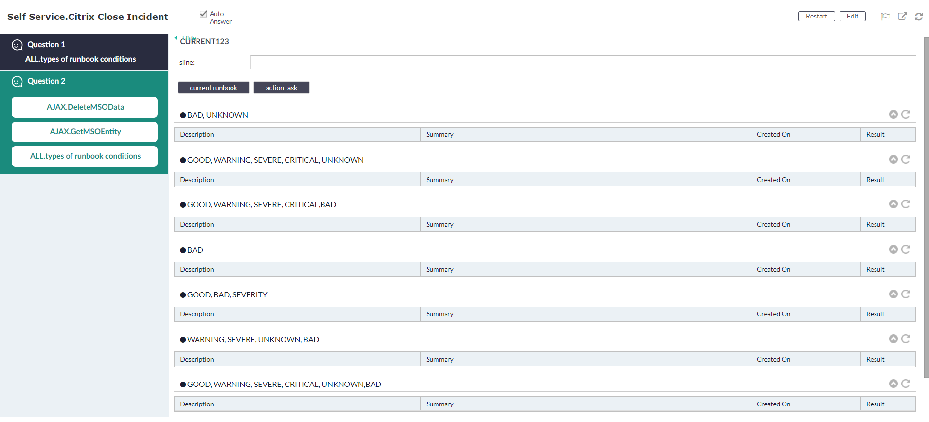
Do not confuse the "Developer View" with the "Decision Tree Viewer", which is what non-developers see as they run through the decision tree.
Notice that all the questions, with answer choices, are listed on the same wiki page. In the Decision Tree Viewer;
- each question is listed on the left-sidebar as you progress through a model pathway
- only the current question or prompt displayed in the main page area.
When running a multiple-question decision tree model (with questions leading to other questions), a wiki document will be created with the same name as the decision tree Root document. This new document serves as a placeholder that stores all question-to-question user decisions for that model.
Decision Tree Builder Interface
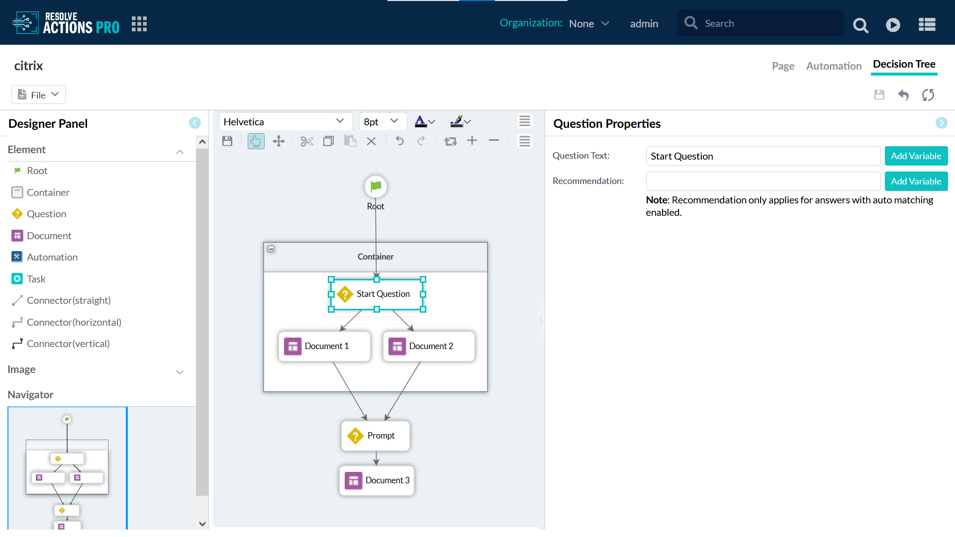
The Decision Tree Builder interface consists of five sections. In addition to the main work area, the other four panels are:
- The Designer panel lists available model elements to use in the work area.
- The Mini-map shows the entire work area at a smaller scale
- The Editor toolbar at the top of the screen has standard icons for formatting text
- Properties allows you to enter or change parameters associated with each element.
Decision Tree Builder Designer Panel
The Library panel in the upper-left of the Designer Panel displays a list of model elements as shapes to use to build the decision tree model. To create a decision tree model, click-and-drag the desired element icon to the work area.
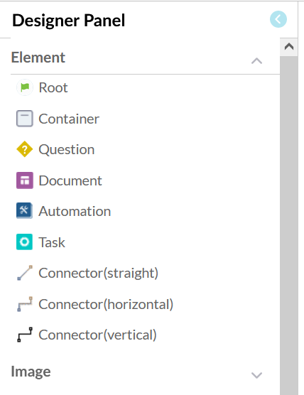
A decision tree automation model always starts with a Root node element, which branches out to questions and documents, connected by selected answer paths. Information about the process of creating a model can be found in Decision Tree Modeling.
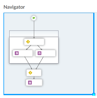
Decision Tree Builder Navigator
In the lower-left of the Designer Panel is a Mini-map that zooms out to show the entire work area at a smaller scale. You are not bound by the space currently shown in the main work area, but can create models larger than the display.
As your decision tree model grows beyond the borders of the main work area, scroll bars will appear and help in navigation (you can also use the Pan function in the Editor toolbar to navigate the work area). However, the mini-map can tell you, at a glance, where you are in the model. In the mini-map, a blue box shows the current field of vision being displayed in the main work area.
To move the blue box and change what part of the model to show in the work area:
- Hover the cursor anywhere over a border (except the corners) until the Moving Cross cursor shows.
- Click-and-drag to move the blue box to quickly navigate around the work area.
You can recenter the Navigator blue box by selecting it and move it over a specific part of the concentrate on a specific area.
Resizing the blue box essentially zooms in or out the display of the model in the work area. To resize the blue box, hover the cursor over the light blue square corner in the bottom-right of the blue box until the Hand Pointer icon shows. Click-and-drag the corner of the blue box to decrease the box (zooming in and enlarging the model to fill the work area) or increase the box (zooming out and shrinking the model).
Decision Tree Editor Toolbar
It can be difficult to see what you are typing while editing a decision tree model in the work area. Formatting text is one way to ease model development. The Editor toolbar at the top of the Decision Tree Builder has icons for formatting the text in the model only. These text-formatting icons have functions similar to those icons found in typical text-editing software.
The most important icon to remember is the Save icon. If the model has been modified but not yet saved, an asterisk (*) will appear next to the decision tree name as a signal that changes are unsaved.
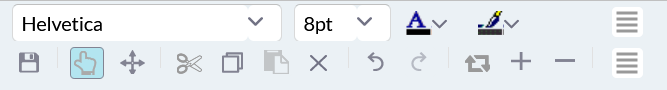
Hover the cursor over the other Editor toolbar icons to display their labels.
In read-only mode, some of the toolbar icons are unavailable.
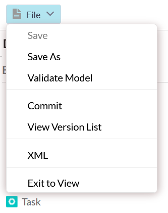
The major item in the File menu icon is show "XML". This option displays the XML code for the decision tree in a separate browser tab, and allows quick copy-and-paste for inserting the decision tree model elsewhere.
Auto-Events Options
There are four additional features added to Decision Trees.
- Selecting an answer can now lead to automatic execution of a series of Runbook or Action Tasks, and will eventually land in a wiki page.
- Question and answer can be dynamically constructed by substituting value of predefined WSDATA variable.
- A Decision Tree layout and format of can be customized.
- A question can be automatically answer if all information needed to fulfil the evaluation are known. The decision tree will automatically advance to the next step.
Auto Answer Enable/Disable
There is a system property (Main Menu > System Administration > System Properties) available called dt.option.isAutoAnswerDisabled. This directs the system to do evaluation for Auto Answer (by default), or not, depending on the value of the property. To overwrite this setting, select/deselect the checkbox located in File View setting in Decision Tree Edit screen.
Feature 1
This option allows Runbook and Action Task to be executed when an answer is selected.

Figure 20 – Auto Answering Option Example
In the example above, the answer path for "Answer 1" (straight line from first question to 2nd question) contains three parts:
- ActionTask "ssh Connect"
- runbook "NEW Process"
- document "System.Doc"
When the answer 1 is selected during execution, the task ssh Connect and Runbook "New Process" will be executed asynchronously one after another then the content of "System.Doc" will be displayed.
Feature 2
This feature allows a question and answer to be dynamically constructed using WSDATA substitution.
During execution of the decision tree, this answer will be replaced with current value of WSDATA with key "customer Name". The value need to be set manually or by automation before it is used in substitution.
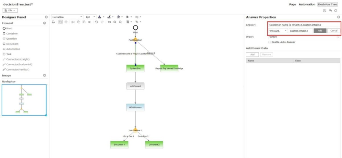
Figure 21 – Runbook "New Process"
Feature 3
The decision tree layout can be configured through the option which can be accessed through File menu.
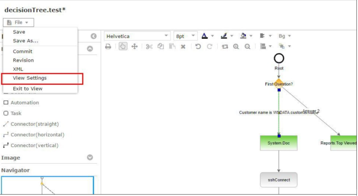
Figure 22 – View Setting
You can rearrange question so that they can be displayed on the top or bottom or have a different color and font for this question and answer in this decision tree.
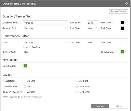
Figure 23 – Decision Tree View Settings
Table 4 – Decision Tree View Settings
| Icon | Description |
|---|---|
| Question Answer Text | |
| Question | Allows you to select a font, color, and size. |
| Answer | Allows you to select a font, color, and size. |
| Confirmation Button | |
| Selections | Allows you to select a font, color, and size. |
| Background Color | Allows you to select color used in the background. |
| Navigation | Allows you to select color used in the background. |
| Layout | |
| Navigation | Radio button: allows you locate this selection either right or left. |
| Question Box | Radio button: allows you locate this selection either top or bottom. |
| Answer Layout | Radio button: allows you locate this selection either vertical or horizontal. |
| Confirm | Saves the settings. |
| Close | Ends the operation and closes the popup window. |
Decision Tree blow is configured to display navigation on the left and question box at the bottom.
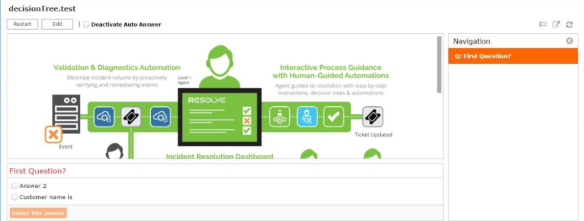
Figure 24 – Decision Tree View Settings Example
Feature 4
A new capability that automatically answers questions and move to the next step, if enough information to answer the question is known. This option is can be enabled in answer property panel for that answer. This can dramatically speed-up the Decision Tree execution allowing operators to focus on resolving the more ambiguous cases. The ability to suggest an answer to a human operator if:
- no definitive answer can be found
- but there are close comparable alternatives.
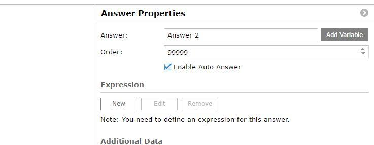
Figure 25 – Answer Properties
Table 4 – Answer Properties
| Icon | Description |
|---|---|
| Answer | Enter the variable name and select Add Variable. |
| Order | Determines the order of execution (from 1-99999). |
| Enable Auto Answer | Turns on the Auto Answer feature. |
| Expression | There are three command choices: New—creates a new expression Edit—allow the selection to be changed Remove—selection is deleted |
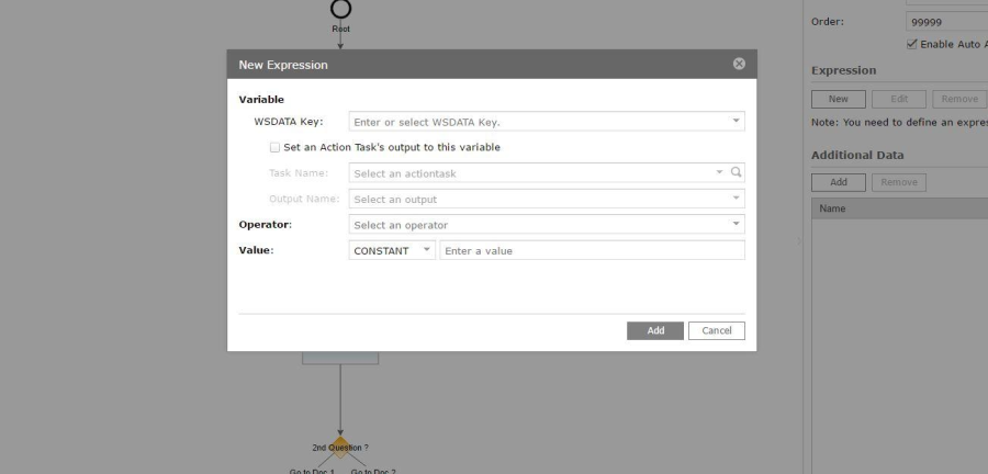
Figure 26 – New Expression
Table 4 – New Expression
| Icon | Description |
|---|---|
| Variable1 | |
| WSDATA Key | Enter or select a WSDATA Key from the pulldown. This facilitates integration between Action Tasks and other decision components by selectively copying the necessary value into WSDATA which is a persistent storage shared by all components. |
| Set an Action Task's Output | Check box that sets the Action Tasks output to the selected variable. |
| Task Name | Select an Action Task from the pulldown or search. |
| Output Name | Select an output from the pulldown or search. |
| Operator | Select an operator from the pulldown. |
| Value | Select a constant and enter a value. |
This assignment only applies for any Action Task or automation.
- Operator: currently supported operators are =, !=, >, >=, <, <=.
- Value: this is a value that the variable is compared to. This can be either a constant or another WSDATA variable.
Example: In this scenario the first answer "Number < 5" for the question "Which path should we go from here?" has auto answer enabled.
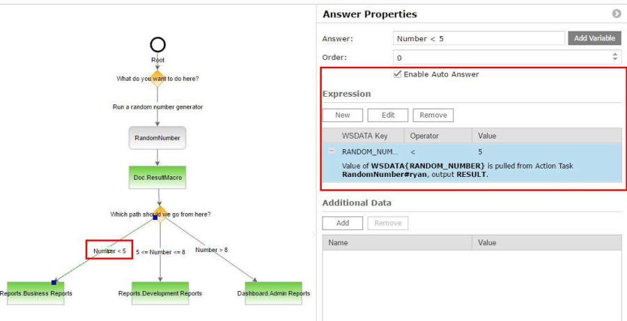
Figure 27 – Auto-Answer Example
This answer will be auto selected by the system when OUTPUT RESULT from "Random Number", which is already executed from the previous question has the value less than 5.

Figure 28 – Auto Selected Value
If there are more than 1 matched answer, system will not pick any answers but instead add indicator next to matched answers.
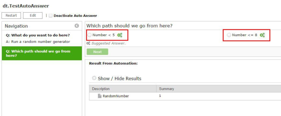
Figure 29 – Indicator Added
Previous example is modified, now since the result is "1" and both answers are matched.
Example: In some scenarios within the decision tree context, data must pass from one question to another.
For example, you can have the first question:
- Obtain customer information
- Run some validation
- Decide how to proceed in the next question based on status of the validation
The following steps were used in the past accomplish this (not recommended):
- Set up an Action Task to assign the output of the validation to WSDATA, since WSDATA is global object (within the same worksheet).
- Reuse it again on the 2nd task in 2nd question.
This design might lead to cluster of WSDATA defined in your task and make reusable of those tasks more difficult.
We recommend the following to prevent this condition; make the assignment when you define expression. This method has two advantages:
- It is flexible when choosing key for WSDATA you want to use for that output.
- It also keeps the action task modular and well contained.
There are two points to remember:
- You need to pay close attention to the WSDATA key. Since they are global variables, they can easily be overwritten by different assignment that using the same key.
- A general rule to apply when for assigning names is using one that is unique while avoiding highly generic terms.
Decision Tree Modelling
A decision tree model is a flowchart-type pattern of connected elements. To create a model, simply drag-and-drop the desired model elements from the Designer Panel on the left-side. Add labels and determine other parameters by right-clicking on each specific element.
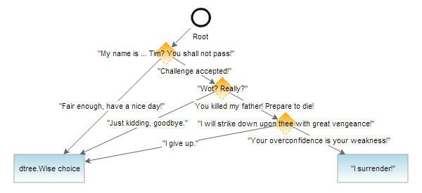
Figure 30 – Sample Decision Tree Model
Every decision tree model starts with the Root node element, symbolized by a black circle. Questions (symbolized by orange diamond nodes) and Documents (blue boxes) comprise the other shapes in any model. All decision tree pathways must end at Document nodes (notice also that the two terminal documents are labeled differently – see Model Element: Documents).
The Answer lines connect the different elements. On connecting different model elements with Answer connectors, go to Connecting Model Elements. For more information about the individual elements and their parameters, see Model Element: Root Node, Selecting Question Type, Ordering Answer Choices, and Model Element: Documents).
The decision tree model, when executed, will display (on the same wiki page by default) all the questions taken and answers given. If the user of the sample decision tree above answered every question to follow down the rightward pathway in the model, then the document page will show:
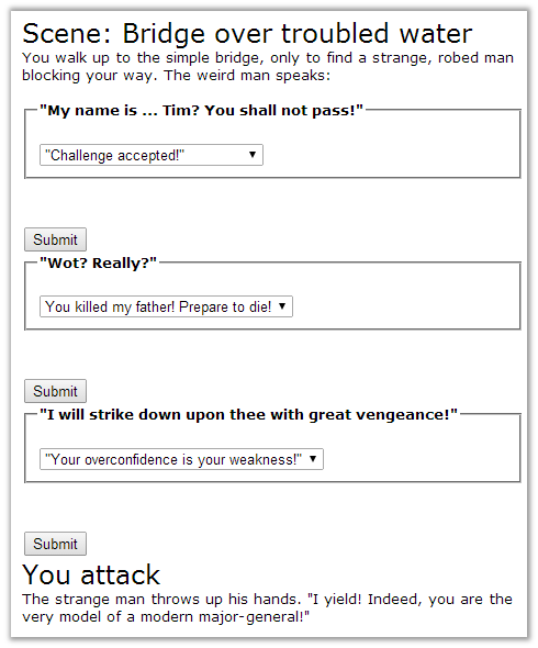
Figure 31 – Sample Decision Tree View, Right Pathway
Connecting Model Elements
To connect elements in a decision tree model, insert the Answer or Answer (Horizontal) lines from the Library. A Document cannot connect directly to another Document. Because the Root is itself a Document element, the first connection from Root must be to a Question element.
There are two methods to connecting elements with Connector lines. The first method requires the Designer Panel to connect model elements:
- Drag-and-drop the Answer line from the Designer Panel to the work area. With the line still selected, hover the cursor over the green endpoint until the hand pointer icon appears. Remember that an Answer line is an arrow with direction, so select the correct endpoint.
- Click and hold down to select the endpoint and drag it to the desired node element. As you drag, a dashed green line shows the potential new path. When you acquire a viable target node, the cursor hand pointer icon will change to the "move" cross icon and the target element (with ID number in small box) gets highlighted in green.
- Release the hold, and the successfully connected Answer line now has one (connected) blue endpoint instead of a previous (free) green endpoint.
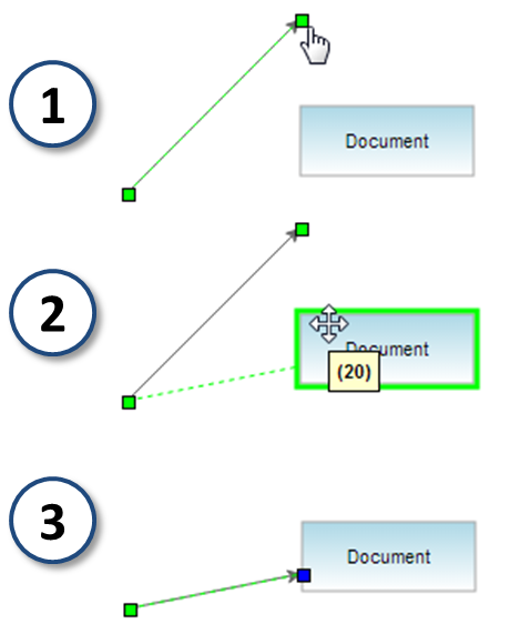
Figure 32 – Using the Designer Panel for Connecting Nodes
This first method is standard, but takes a little time to place the Answer connector in the neighbourhood of the target elements and anchor both endpoints. The second method is a quick shortcut that automatically inserts and connects an Answer line between both target elements:
- Hover the cursor over the centre of the desired element from which you want your connector to start. A blue "goto" arrow icon should appear in the element centre.
- Click-and-drag the arrow to the target element at which you want your connector to end. The element will highlight in green if properly selected, and its ID number will pop up. Notice also the dashed green line showing the new connection path and the change in cursor to the "move" cross icon .
- Release the hold, and the successfully connected Answer connector now has both blue endpoints and automatically connects both elements.
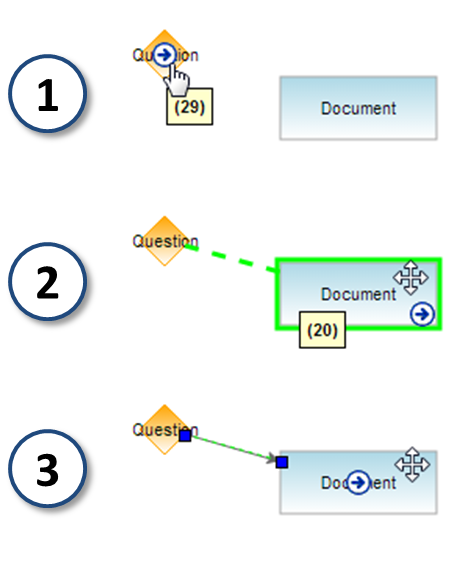
Figure 33 – Shortcut "Go To Method" For Connecting Nodes
The disadvantage to the shortcut connect method is that the "goto" arrow is also a shortcut to copying elements in the work area, and thus risks accidentally copying the starting element rather than connecting it to a target. See Copying Model Elements below about the problems associated with this risk.
Copying Model Elements
Instead of using the copy-and-paste functions in the Designer Toolbar, you can use the "goto" arrow method to copy elements in a decision tree model. To quickly copy an element:
- Hover the cursor over the center of the desired element to copy and wait for the blue "goto" arrow icon to appear in the element centre.
- Click-and-drag the arrow to any space not occupied by another model element (no model element is highlighted in green, and the cursor remains normal).
- Release the hold, and a copy of your original element will be created and automatically connected to the original.
- If the arrow was not dragged a sufficient distance from the original, then the copy could be placed over the original (notice the different element ID number) and the copy will appear as if it were the original element!
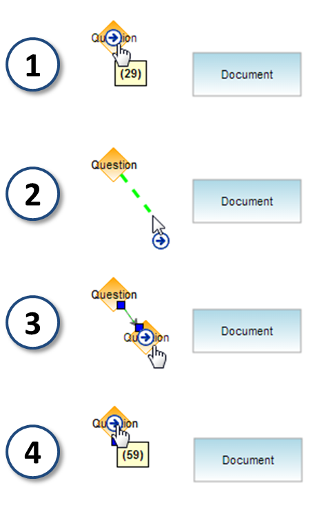
Figure 34 – Shortcut "Goto" Method for Copying and Connecting Model Elements
If using the "goto" shortcuts to connect two pre-built model elements or to copy an element, ensure that you move the cursor a distinct distance away from the original starting element. Otherwise, the potential exists for accidentally making a copy, connecting it to the original node, and placing it over that original.
Be careful not to double-click on the "goto" arrow, as that could trigger a quick copy-and-paste-over. When you attempt to connect from the original node again, you are actually connecting from the copy; in effect, you have inserted a duplicate element into the pathway.
Use "goto" shortcuts for small decision tree models or during the early stages of larger models. At a later development stage of a complex decision tree, it is best to use standard methods because unwanted duplicates might be difficult to trace. For other considerations in creating decision trees, see Decision Tree Guidelines and Restrictions.
Inserting Model Elements
If you want to create or move an element in a decision tree model, and insert it into the connecting pathway between two other elements, you must change all the Answers. You can use a shortcut instead of deleting the old answer line; inserting the new element, then creating two new lines to connect the inserted element.
To quickly insert an element into a pathway, simply:
- Drag (click-and-hold) the element onto the pathway (make sure not to select and highlight the element itself, and not its blue "goto" arrow). The connector pathway will highlight in blue when properly targeted.
- Drop (release the hold) and insert the element over the proper connector.
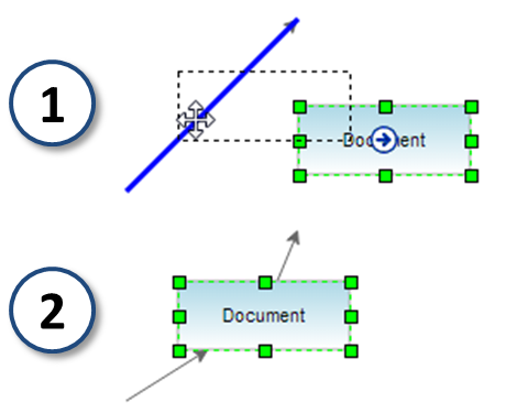
Figure 35 – Shortcut "Goto" Method for Inserting Model Elements
Decision Tree Builder Elements
There are four elements to a decision tree model:
- Root
- Questions
- Connecting Answers
- Documents, which can be either pass-through or terminal nodes.
- Automation
The Decision Tree Builder also allows the use of Model Aid: Containers to compartmentalize related elements. All elements can be accessed through the Builder Library.
Table 6 – Designer Panel
| Element | Basic Rules |
|---|---|
| Start of a decision tree; must connect to a Question | |
| End of a decision tree; must connect to the tree. | |
| Event contains a Display Name, Input or Outputs, three Merge choices (All, Any, and Targets), | |
| Text box used for labeling. | |
| A Container is not an actual model element itself, in terms of executing the decision tree and presenting text or referencing a Document. Similar to Containers in Runbook automation models, Containers in decision tree models do not affect the logic of the model. They help developers organize a decision tree model into more easily understood and manipulate sub-units. To add a Container to your model, click-and-drag the Container symbol from the Designer Panel to the work area. | |
| A decision tree model can call on Runbook automation by referencing the appropriate name as a Document object. This is common in troubleshooting decision trees that use Runbooks to run diagnostics or solutions. Documents can be used in multiple decision trees, or even referenced multiple times within the same tree. Documents can be "pass-through" Documents in the middle of the model, or terminal nodes of a decision tree model. All the pathways of a decision tree must end in Documents (although such endpoint Documents can themselves be decision sub-trees). | |
| Adds the Task Wizard to allow you to "Select an Existing Task" or create a new task. | |
| Provides a Question (entered into the model element label) to be displayed on the page | |
 | There are three types available to allow multiple path shapes. Provides different answer alternatives for a Question, connecting it to other Questions or Documents; without an answer, the label of the connected Document or Question is shown (loops are possible). |
| The Document reference can be regular wiki page or another (embedded) decision tree; can connect to further Questions, but each decision tree pathway must end with a terminal Document |
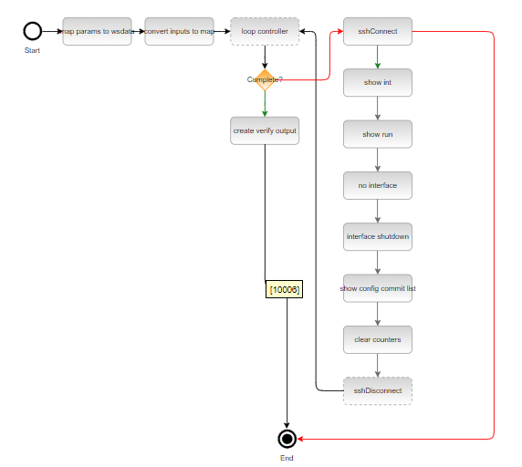
Figure 36 – Sample Decision Tree, Model
Basic information about creating the layout of a decision tree can be found in Decision Tree Modeling. In designing a decision tree model, right-click on a model element to bring up important options, such as descriptive element labels or Document links which appears as a panel on the right side.
A useful tool o is the "Align" function. Select the model element you wish to arrange, look for the cross alignment icon, then choose the desired alignment reference to share (horizontal or vertical borders lined up red crosshairs appear).
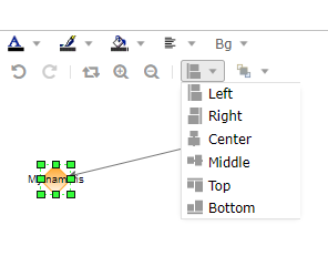
Figure 37 – Decision Tree model right-click menu: "Format" option, "Align" Function
Model Element: Root Node
The Start node starts every decision tree model and represents the initial Root document page created by the developer to start the model in the first place. To add a Root to your model, click-and-drag the Root symbol/name from the Designer Panel to the work area.

Figure 38 – Decision Tree Builder Library
Because it is the first wiki page that a decision tree user will see, try to include introductory material in the Start page source code. By definition, the Start element in every model must connect to a Precondition to start the decision tree process, as seen in the sample decision tree.
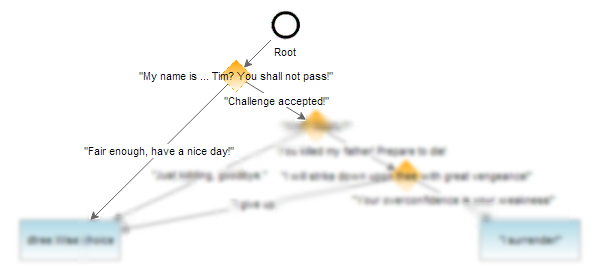
Figure 39 – Sample Decision Tree Model, Root Node With First Question Unblurred
This initial Root element, when viewed in the page, thus sets the context of the decision tree and introduces the first question:
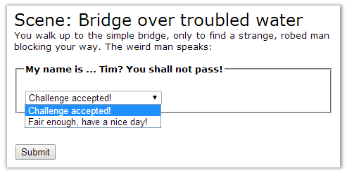
Figure 40 – Sample Decision Tree, Root Document Page View
The Root document page was developed earlier upon model setup, when the decision tree was first created to access the Decision Tree Builder. The sample Root page source code below has two sections:
- the upper section highlighted in red box
- a lower section selected in blue text highlight
The red-boxed code is the wiki markup code rendered in the page view above.
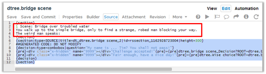
Figure 41 – Sample Decision Tree, Root Document Code
Builder-generated Decision Sections
In the sample Root page code below, taken from a decision tree, note in the separate blue-highlighted section code that the section includes {decision} tags. This section was added by the Decision Tree Builder, and therefore did not exist when first writing the Root code on setup. Sections created by the Builder must not be modified by users, and are prefaced with the code comment "GENERATED CODE: DO NOT MODIFY".
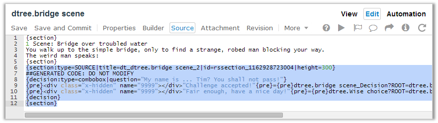
Figure 42 – Sample Decision Tree, Root Document Code
These Builder-generated decision sections are used by Actions Pro to associate referenced Document objects (which exist outside the decision tree model) with the decision tree and connected elements. For example, if an actual Document object (not model element) referenced by a decision tree model were moved or renamed, then the Root would be automatically updated. Developers are freed from having to edit or save each subsequent Document.
- Copying a Document object that is not a Root will remove the decision section in the new copy.
- Deleting the Root document will remove all decision sections in referenced Documents, but will not delete the Documents themselves.
Model Element: Precondition Nodes
The Precondition element in a decision tree model displays a question or prompt on the wiki page. To add a Precondition to your model, click-and-drag the Precondition symbol/name from the Designer Panel to the work area.
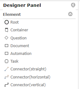
Figure 43 – Decision Tree Builder Library
The actual question text to be displayed on the wiki page is the model element label. Within the model, the question label appears over the Question diamond symbol. There are two methods to enter the question text.
- Click on the Precondition element to type in the label. The entry popup up menu appears at the right.
- Double click and the text box naming it appears allowing you to rename it.

Figure 44 – Precondition Model Element
Enter the required: Display Name, Merge (All, Any, and Targets), Expression.
Selecting Question Type
The "Question Properties" provides a choice for how to display connected Answers in the wiki page. Answer choices are displayed in a drop-down menu by default, but can be changed to list in as radio buttons. In the right-click menu, go to "Question Type" to flash the two choices.
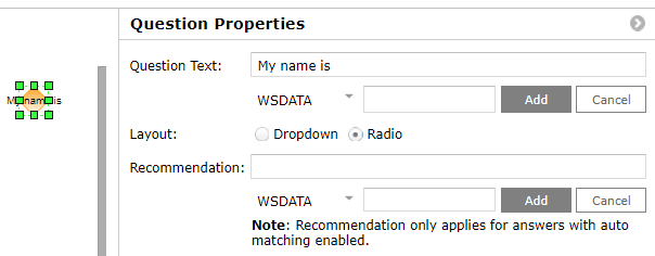
Figure 45 – Question Model Element Properties
Model Element: Answer Connectors
The Answer element connects the other different element nodes in a decision tree model. To add an Answer connector line to your model:
- Click-and-drag either of the Answer symbols from the Designer Library to the work area.
- Connect the line endpoints to the desired model elements (see Connecting Model Elements on the modeling process).
Questions can have multiple answers as complex as needed.

Figure 46 – Decision Tree Builder Library
The Connector line label shows the actual text that will be displayed as an answer choice for a connecting Question.
- Changing the text on the connector changes what answers get displayed for each Question.
- If you do not input any answer text on the connector (the Answer line is blank), then the answer choice displayed in the wiki page will default to the label of the following linked with another element.
There are two methods to enter answer text into the Connector label.
- As a shortcut, double-click on the Answer line to type in the label. Double-clicking will bring up a flashing text caret that appears on the model element itself, rather than pop up a separate dialog box. As with double-clicking any element, be careful not to accidentally copy-and-paste-over the element (see Copying Model Elements).
- In the second method, right-click on the Answer line and select "Edit Properties". In the "Edit Properties" dialog box, type the answer choice text into the "Label" field.
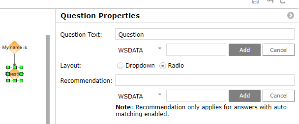
Figure 47 – Answer Model Element, Properties
Ordering Answer Choices
A Question element will list all its connected answer choices in either a drop-down menu or as radio buttons. By default, these choices are listed in alphabetical order.
- To change or set the order of the answers, change the element ID numbers for all the relevant Answer connectors through the "Edit Properties" dialog box. The answer choices will be displayed in order from lowest to highest based on the connector ID.
- To quickly check the ID numbers for any model element, simply hover the cursor over the element for a moment, and its element ID number will appear in a small box. The numbering scheme increments depending on how many connectors have been drawn previously.
Model Element: Documents
The Document model element in a decision tree model represents a link to an Actions Pro Document or Runbook. To add a Document to your model, click-and-drag the Document symbol from the Builder Library to the work area.

Figure 48 – Decision Tree Builder Library
- Documents must connect to Question elements; they cannot connect directly to another Document in the model.
- You can insert a Question with only one connecting answer line between two Documents. Such a Question would serve as a prompt rather than question with a menu of answer choices.
- As a Document itself, the Root cannot connect directly to another Document (the initial Root wiki page serves this purpose).
The Document label can display either a descriptive label or the actual name of the linked Document object. However, using the Document name may not clearly represent its function within the decision tree model. Entering a descriptive label provides more meaning. Another consideration is that any incoming Answer line, if that connector lacks a label, will default to use and display in the wiki page the label of the connected Document.
There are two methods to enter a Document label.
As a shortcut, double-click on the Document box to directly type the Document object name (including full namespace or module name) into the label. Double-clicking will bring up a flashing text caret that appears on the model element itself, rather than pop up a separate dialog box. As with double-clicking any element, be careful not to accidentally copy-and-paste-over the element.
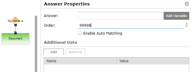
Figure 49 – Document Element, "Edit Properties" Dialog Box
Any editing changes made to the Document, such as moving or renaming, will update the parent decision tree. This allows developers to be free from having to edit or save the parent decision tree as well, although the browser will need to be refreshed. Because Documents exist separately from the decision tree model, deleting the Root document will not delete the linked Documents themselves.
A decision tree model can call on Runbook automation by referencing the appropriate name as a Document object. This is common in troubleshooting decision trees that use Runbooks to run diagnostics or solutions. Documents can be used in multiple decision trees, or even referenced multiple times within the same tree. Documents can be "pass-through" Documents in the middle of the model, or terminal nodes of a decision tree model. All the pathways of a decision tree must end in Documents (although such endpoint Documents can themselves be decision sub-trees).
Once a decision tree has run its course, a user will remain on the displayed page. It is possible with scripting to send the user away from the page (it requires knowledge of JavaScript and the Actions Pro infrastructure, and should only be attempted with help from Support). During the execution of a decision tree, Documents with scripting can be used to create separate pop-up windows, which can be styled differently from the displayed in-line decision tree page.
Decision Sub-trees
Since the Root element of a decision tree is itself a Document, a decision tree can reference a Document element anywhere in its model that calls on another decision tree. In other words, decision trees can have embedded sub-trees. Often, parent trees end their pathways by calling on other sub-trees to complete the relevant task.
For example, a decision tree that serves to help customers find movie show-times might ask for the customer location.
- Given the city name, the parent tree will then reference a first sub-tree responsible for all theatres in that city.
- That first sub-tree could even call on a second sub-tree that corresponds to a specific theatre, which would ask questions about current movies.
- Only the second (theater) sub-tree would need to be updated regularly with new movies and times; the first (city) sub-tree would require updates whenever a new theater opens or an old one shuts down.
As a Document cannot directly connect to another Document, a setup Question is required before each endpoint referencing a completion sub-tree.
Model Aid: Containers
A Container is not an actual model element itself, in terms of executing the decision tree and presenting text or referencing a Document. Similar to Containers in Runbook automation models, Containers in decision tree models do not affect the logic of the model. They help developers organize a decision tree model into more easily understood and manipulable sub-units. To add a Container to your model, click-and-drag the Container symbol from the Designer Panel to the work area.

Figure 50 – Decision Tree Builder Library
Usually, Containers hold distinct groups of elements that can be collapsed or expanded in the work area display to make the overall model easier to see and understand. Containers can be cut-copied-pasted, so a cluster of model elements placed inside a container can be quickly reproduced. Deleting a Container will delete both its content objects and all connectors to those objects.
To place a model element or elements inside a Container, click-and-drag the elements you want into the Container, but do not release the hold until the Container is highlighted in blue. When you successfully put the elements into the Container, a small minimize "-" button will appear in the upper-left corner of the Container box. To take elements out of a Container, simply highlight them and drag them out.
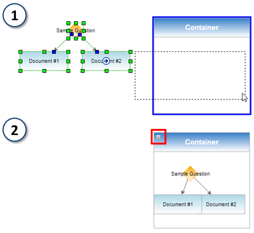
Figure 51 – Placing Elements Into Containers, with Minimize Button
When a Container is minimized, it will collapse into a small box and a maximize "+" button will replace the minimize button. The position of the new minimized Container will share the same upper-left corner point as the original box.
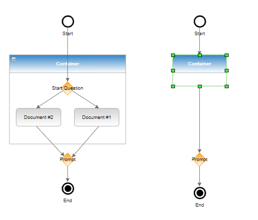
Figure 52 – Minimizing Container
As with model elements, Containers can be labeled using a:
- double-click shortcut
- right-click menu's "Edit Properties" dialog box.
With either method, double-click or right-click on the "Container" bar at the top of the box and not inside the Container area. Since a Container serves no logic function in a model, Container labels are solely for convenience.
Automation
This model element in a decision tree model represents a link to an Actions Pro Runbook. It allows you to add or create a new Runbook.
When the Main Model tab is selected, in Automation mode, the "Edit" mode the Designer Panel/Element panel appears allowing you to select the Automation icon and move it into the decision tree model.
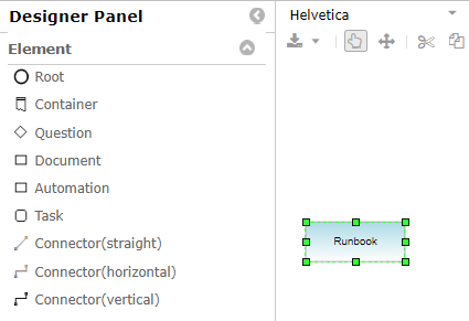
Figure 53 – Automation Element
On the right hand side of the panel is the New Runbook Properties menu.

Figure 54 – New Runbook Properties
Clicking on the Select A Runbook button allows you to choose and add a previously created Runbook.
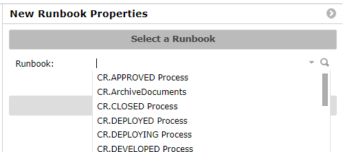
Figure 55 – Select Automation
The other option is to Create a new Runbook.
- Select the Namespace.
- Choose a name.
- Select Create.

Figure 56 – Create a new Runbook
Decision Tree Guidelines and Restrictions
Some of the important decision tree modelling rules mentioned in other documentation bears summarizing here:
- Always start with the Root node, which represents the main Wiki Document.
- A Document cannot link to another Document without a Question in between.
- Decision trees can be embedded as Documents in other decision trees.
- Be wary of model loops and recursions if re-using sub-trees and Documents within the same model or looping an Answer line back to a previous Document.
- If using "goto" shortcuts, then mind the copy-and-paste-over error.
- Builder-generated decision sections and tags (Questions) should remain untouched.
- Decision tags (Questions) are visible only if you navigate via the decision tree from the Root to the Document, and will not appear if viewing the Document independently.
- Conversely, copying a Document that is not a Root will create an independent Document unassociated with any decision tree (the decision sections are not copied over).
- If you design a multiple-question decision tree model, a wiki document gets created with the same name as the decision tree Root document appended by "_Decision" and serves as a placeholder that stores all question-to-question decisions for that model.
Some design considerations to keep in mind:
- Individual decision trees should be kept small and simple to improve maintainability.
- Proper naming and labelling of decision trees and elements help maintainability.
- Decision tree design should be based on use cases.
- Path analysis is an important part of tree design (a path is the series of Questions and Documents from Root to a specific target Document).
- Be careful how users interpret Questions and Answer choices.
- If embedding Runbook automation, provide feedback of results to the viewer by displaying automation progress results onto the wiki page (consider the {result} and {detail} wiki markups).
- Help information can be added to Documents, either as links or buttons to pop-up help windows or as an Answer choice to request help (with the exit looping back to the original Question or Document).
- Consider how and when a user finishes or exits a decision tree, whether to close the window or send the user to a menu, start page, or another location, and if the exit action is automatic or invoked by the user.
- Variable: WSDATA variable that has the key defined. You can also assign OUTPUT from a task to this WSDATA variable during execution by check "Set an Action Task's output to this variable".
The expression form has three parts:↩