Automation Designer Overview
The Automation Designer allows you to define your automation process as a flowchart-like diagram. To access Automation Designer tool navigate from Main menu to Development Tools > Automation Designer. The tool has read-only view and edit view. To start working on the Automation process you need to enter edit mode through the Edit icon in the upper right corner of the Automation Designer. An automation model is created by dragging elements from the Object Library and connecting them together in the main work area.
- Click on any model element in the work area to select it for editing.
- It is important to remember to save the model before navigating away from the Automation Designer. If any of the elements in the Automation designer have been modified but not yet saved, an asterisk (*) appears next to the Runbook name.
The Automation Designer interface consists of three sections:
- Designer Panel – It is comprised of four sections: Element, Image, Connection, and Navigator (shows the entire work area at a smaller scale)
- Work area – the place where the automation is created by dragging and dropping elements, images, connections. Includes a Editor Toolbar panel.
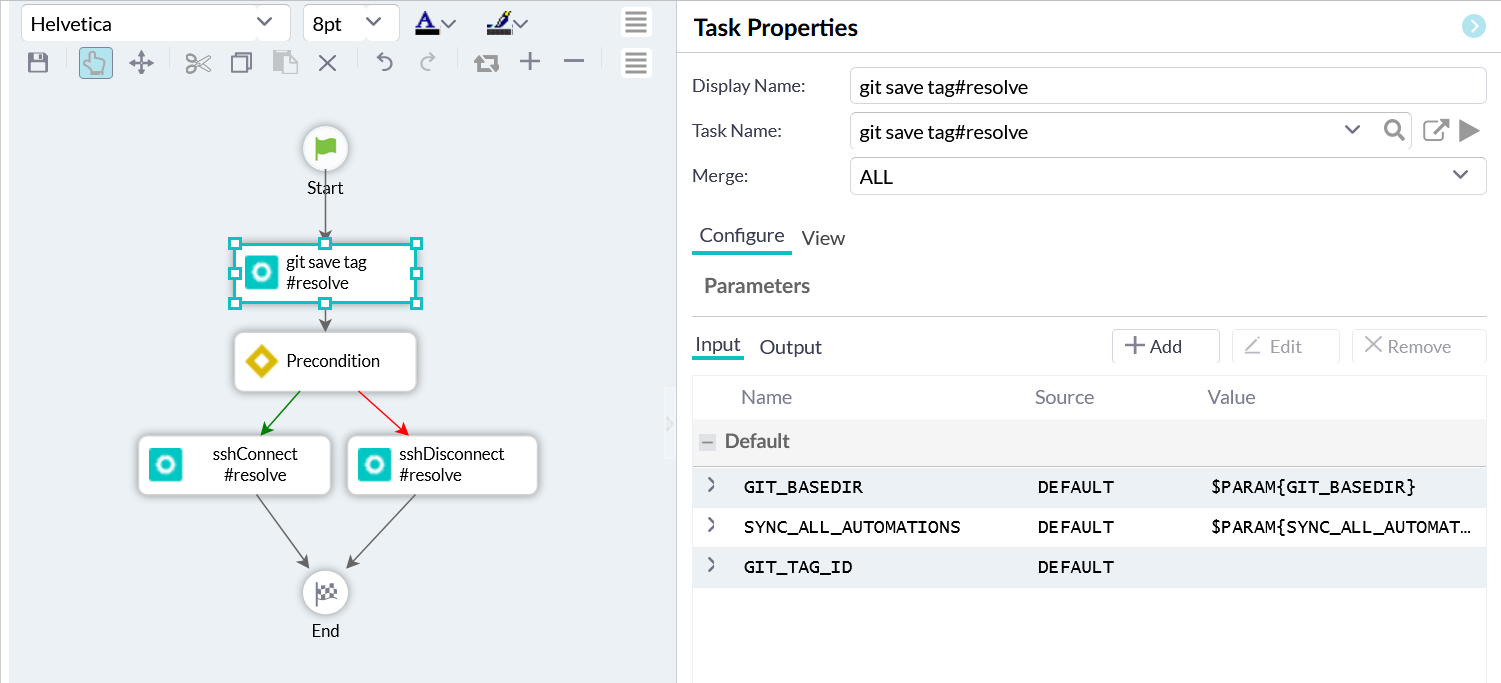
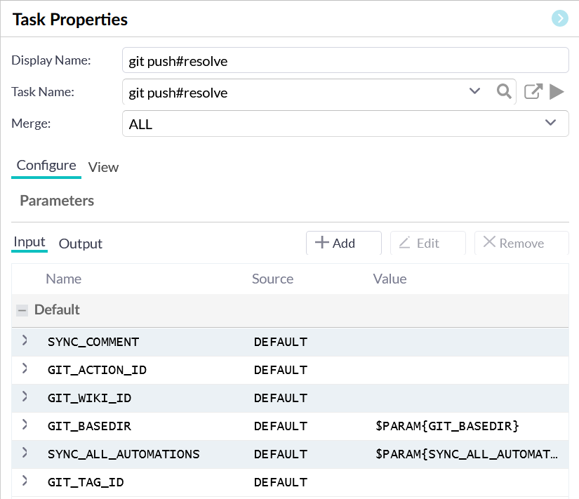
- Properties panel or wizard – visualizes the properties and the parameters of the selected element, image, or connection. Provides ability to assign existing ActionTasks or Runbooks to the automation model. Provides the ability to create an ActionTask or a Runbook from scratch.
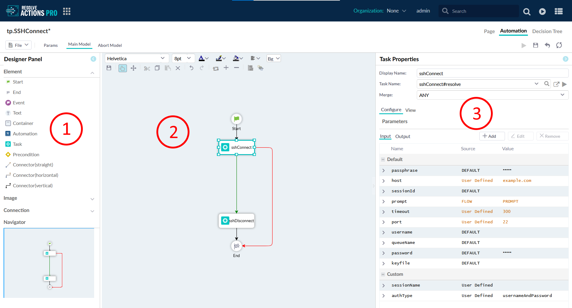
Designer Panel
The Designer Panel takes up the left side of the Automation Designer. To create or add to an automation model, drag-and-drop the desired model icon from the Designer Panel to the work area.
Elements
The Elements palette is displayed by default. It shows a list of model elements as shapes to use to build the Automation model. To add an element to the automation model, drag-and-drop its icon on to the work area. Use the Properties panel on the right to configure the element.
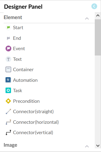
The following table explains the purpose of each element type.
| Element Name | Description |
|---|---|
| Start | Marks the start of the Automation. There can only be one START node. The parameters to the START node are used to define process-level attributes to the Automation execution (for example, PROCESS_TIMEOUT). |
| End | Terminates the Automation. There can be multiple END nodes; however, as soon as one such node is reached, the entire Automation process completes and all resources and state information is cleaned up. |
| Event | Allows the Automation to halt until a specified event is received. This is often used to interact with end-users through the form-based workflows as well as external systems. For an example, an approval email may be required to be received before the Automation may progress to the next set of steps. |
| Text | Allows annotations to be included on a process. |
| Container | Allows grouping and "collapsing" of parts of the automation model for viewing convenience, with no functional or execution effect. Similar to containers in Decision Tree models. |
| Automation | An imported or embedded Automation, also called a sub-Automation that executes as part of the parent process with access to the same context/data. It behaves as though its model were copy-pasted into the parent. All incoming links from the parent Automation to the sub-Automation behave as directly connected to the sub-Automation’s START node, while all the sub-Automation’s End nodes are outbound links continuing into the parent Automation. |
| Task | Represents an ActionTask to carry out an action and assessment of results (or just the assessment with no inherent action, as with Assessor-only ActionTasks). Assessment includes: interpreting activity completion or abortion, success or failure (condition), and severity (if required); formatting and selecting information to present to end-user; determining control flow logic. Tasks are connected with process flow logic to define the activities executed by the Automation. |
| Precondition | Allows explicit state variables to be evaluated and used to control the flow of execution of the Automation. For example, an ActionTask may save variable values as part of an assessment which is then used later on in the Automation to determine the control flow. |
| Connector (straight, horizontal, vertical) | Connectors are directional lines (arrows) linking model elements. The links also control the execution flow with dependency conditions which are assessed by the source ActionTask object.
|
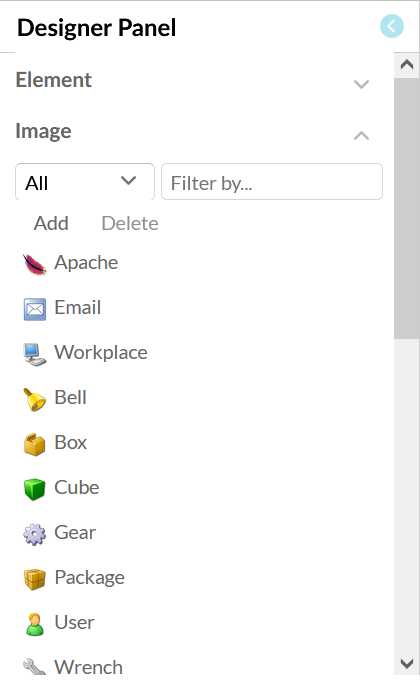
Images
The Image section of the Designer Panel displays a list of model elements with preset icon images. These elements are all standard Task objects, but the icons are intended to help distinguish them visually in the automation model. They are useful in adding to the look and feel of a model for presentation purposes.
- This feature panel allows you to add or remove custom images.
- You can expand/contact the feature using the arrow icon.
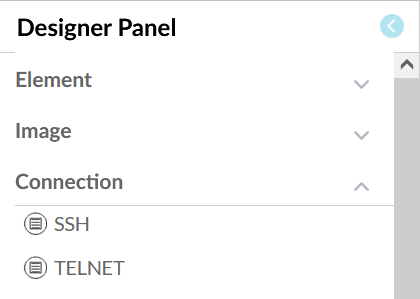
Connection
A connection in the Automation Model is used to make a SSH and Telnet connection, same as a gateway or an adaptor, to an external machine. The automation can also connect the RSRemote instance to the local machine, usually to execute OS commands. Automation Designer connections are actual connection to local or external servers.
Select the type of connection you need, move the cursor over to the field and release the mouse and the new connection will appear. When adding a connection, a popup window provides different settings for the connection.
Navigator
In the lower-left of the Designer Panel, the Mini-map zooms out to show the entire work area at a smaller scale. As the model grows beyond the borders of the main work area, scroll bars will appear and help in navigation (you can also use the Pan function in the Editor toolbar to navigate the work area).
Resizing the blue box zooms in or out the of the model display in the work area. To resize the blue box:
- Hover the cursor over the light blue square corner in the bottom-right of the blue box until the Hand Pointer icon shows.
- Click-and-drag the corner of the blue box to decrease the box (zooming in and enlarging the model to fill the work area) or increase the box (zooming out and shrinking the model).
- You can also use the Zoom buttons on the Editor toolbar for zooming in/out and to reset the display size.

Work Area
To create complex automations for a Runbook, use the Automation Designer available in the Automation tab view of the wiki page. If the models have been modified but not yet saved, an asterisk (*) appears next to the Runbook as a signal that changes are unsaved.
The Automation Designer makes validation checks every time you save your model. If the validation fails, the Automation Designer will show the Invalid Model button in the toolbar that you can click to view the list of errors that if found.
Work Area Toolbar
The local toolbar in the Work Area provides different tools for working with the Automation Model’s graphical representation. Formatting text appearing on the model is one way to use it. It also offers some tools for manipulating the shapes in the model. Use the hamburger menus to view the full set of tool.
Properties Panel
You can change the configuration of objects that appears in the Work Area Inside using the Properties Panel. The Properties Panel appears on the right when you click an object in the Work Area. Depending on the object type, the panel shows different properties or even no properties.
Common Interactions
Quick-Copying Model Elements
Instead of using the "copy-and-paste" functions in the Editor Toolbar, you can use the "goto" arrow method to copy elements in an automation model. To quickly copy a model object:
- Hover the cursor over the center of the desired object to copy and wait for the arrow icon to appear in the object center.
- Click-and-drag the arrow to any space not occupied by another object.
- Release the mouse button.
A new instance of the original element type appears and connected to the original. The new element does not preserve the original’s settings.
Always leave sufficient distance between the original and the drop location, otherwise the copy could end up covering the original.
To check for overlapping elements, cycle through the automation model with the left or right arrow keys to highlight each element.
Configuring Element Properties
You can use the Properties Panel to configure objects in your Automation Model. Is opens on the right side of the screen.
Use any of the following methods to configure an object’s properties:
- Left-click the object in the work area.
- Right-click the object in the work area and then select <Object Name> properties from the context menu.
Renaming an Element
Use any of the following methods to rename an object in the work area:
- Double-click the object in the work area and type in the new name.
- Click the object to open its Properties Panel and type in the new name in the Display Name field.